This page is a summary of a few things I made over
the years, in roughly chronological order.
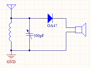
Crystal Set
Back in the 1950's, most kids started out building a basic crystal set.
I was fortunate in that my parents' house had a large antenna & a good earth, put in
when the house was built in the 1920's, & radios were far less effective than they
later became. I paid for the parts for the set, & my father matched me by providing a pair
of proper high-impedance earphones. I had ordered the parts from my local radio shop, & was
quite disappointed when they supplied a ready-wound tuning coil, rather than the spool of
wire I had expected (I intended to wind the coil myself.) Nevertheless, it worked very well.
It was built in an old wooden cigar box.
If you want to try this yourself, 2 tips:
- Use a germanium diode if possible: it is far better than silicon for this. If you have
to use silicon, it may be worth trying a Schottky type.
- The earphones must be a high-impedance type (mine were 4kΩ). Low-impedance types,
as used for computers, personal music players etc., just will not do. You may be able to
use a small audio step-down transformer, I haven't tried it myself.
|
 |
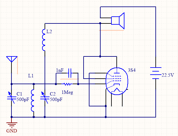
D5B Receiver
This was a logical progression from the crystal set. The parts were bought as a kit;
I simply had to assemble it. I have used an available pentode symbol: the 3S4 tube is
directly heated, so there is no separate heater. The schematic is from memory, &
very much E&OE.
The learned will at once recognize the (in)famous super-regenerative
design. A station is tuned in using L1/C1, then a degree of positive feedback is applied by
adjusting C2 (coils L1 & L2 are magnetically coupled.) The danger with this circuit is
that the most sensitive spot has it just on the edge of outright oscillation: it readily
radiates broadband interference. Back then, people didn't worry so much about this, but
today it would be asking for trouble. If you want to experiment with a super-regen, put a
separate RF amplifier between it & the antenna.
As with the crystal set, a high-impedance earphone is required.
|
 |
Tape Recorder
This design was published in the UK magazine Practical Wireless,
February 1961 & following. My build followed the magazine quite closely, the major difference being
the use of a Collaro Studio tape-deck, rather than the Motek which was specified. However it worked
very well. This project taught me the importance of careful layout with high-gain tube amplifiers:
they can readily pick up from their own outputs, & burst into oscillation.
Simplex-III
The 8-bit computer I built back in
1976; it has its own page.
P112
A Z-80 powered CP/M board, sized to fit on a 3-inch disk drive.
It also has its own page. Although I no longer sell this, it still has
a following.
Igor-II
This is a vacuum-tube audio
amplifier, built around 2007. An OTL
design using ex-Soviet 6C33 output tubes directly connected to the
speakers, it delivers 25+25W continuous power.
Why was it named Igor? The first breadboard version
used a collection of miscellaneous transformers to generate the
numerous voltage rails, & looked like something from a 1930's
Frankenstein movie. “See Igor, Russian tubes! Now ve shall ze
vorld astound!” (Sorry🙂)
The first version was purely
experimental, & went through several changes in topology. Version
2 settled on a conventional totem-pole output stage, with a
deliberately asymmetrical phase-splitter to compensate for the
different gains in the upper & lower limbs of the totem-pole output
stage.
This
sequence shows how it was built. The mechanical design began with
a 3D model using Solid Edge, from which the sheetmetal drawings were
taken off. The parts were professionally
fabricated, & the external parts powder coated.
The schematic of one
channel is shown. The accompanying “PCB layout” is a
dummy, which was drawn up to assist in planning the component layout
in the chassis.
V1 implements a cascode first stage, which provides
most of the gain.
The phase-splitter, V2, has a very small cathode
resistor (R7), this causes the stage to run unbalanced, with more
gain in V2A than V2B. This compensates for the extra gain provided by
V5, the lower limb of the output block. The upper limb, V4, is a
cathode follower, & so contributes no voltage gain. The cathode
supply (via R9) is switched in the control module, enabling the
controller to provide a “soft-start” function, to avoid
thumps on turn-on.
The cathode follower V3 provides the ability to drive
the output tubes into grid current, so greatly increasing the
available output. R3 & R17 provide some 12dB of negative
feedback.
The power supplies are shown here.
The HT & LT transformers were custom built. Each is controlled by
a solid-state relay, which switches instantly, not on zero-voltage.
The control module uses this ability to soft-start the supplies,
gradually increasing the duty cycle. A slow start is provided for the
tube heaters, & a rather faster one for the HT rails. The edge
connector at centre-right is the control
module.
Control is implemented by software
in an Atmel AtMega-8 microcontroller.
Door Control
A basic remote-controlled garage
door opener. Yes, these are quite inexpensive to buy, but I took
it as a challenge to build one (both the electronic and mechanical
parts) using stuff in my junk box.
The motor came from an ancient
“washing machine” disk drive, feeding a 30:1 worm drive
from the junk box. This is followed by an intermediate shaft (top in
the picture), with a dog-clutch
operated by the large black knob, providing for manual operation.
A commercial 433MHz
receiver feeds the control PCB. The
software is available.
The motor has 2 identical windings
spaced 90°
apart. To start the motor, one winding is powered directly, & the
other received power phase-shifted by a series capacitor. Once
started, the phase-shifted current is stopped, & the motor runs
on one winding. Interchanging the 2 windings runs the motor in
reverse.
The
door motion is sensed by industrial reed switches at the top &
bottom of the track.
Digital Clock
Another simple project, the point
of this one was to include backup via a supercap,
to enable it to survive the too-frequent power outages in the Perth
Hills. 3 copies were built, & used
around the house.
The specification
provides a basic functionality, using 3 rear-mounted buttons. The
software is available.
Soldering Oven
A cheap benchtop oven is
re-purposed to solder SMT circuit boards. Two soldering profiles are
stored in EEPROM, & can be changed by reloading the software.
The original controls were removed, & replaced by
a custom design. A panel was made from the
fireproof material used for electrical switchboxes, & fitted to
the side of the oven chamber. Control components are fitted to this
panel.
Temperature is sensed by a K-type thermocouple,
visible at the right, just under the transformer. The control
PCB uses the same Atmel CPU as my previous projects. The software
is available. Inputs are the thermocouple & panel switches. There
are 3 isolated triac outputs: the 2 heating elements & a fan,
salvaged from an old microwave oven.
Several fine-pitch SMD boards have been successfully
soldered in this oven.
TRIDOX
A 3-dimensional noughts-and-crosses program.